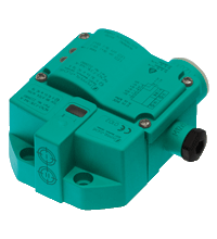
Inductive sensor NCN3-F31K-N4-K
Part number: NCN3-F31K-N4-K
Specification
| General specifications | ||
|---|---|---|
| Switching function | 2 x normally closed (NC) | |
| Output type | NAMUR | |
| Rated operating distance | 3 mm | |
| Installation | flush mountable | |
| Assured operating distance | 0 ... 2.4 mm | |
| Actual operating distance | 2.7 ... 3.3 mm typ. | |
| Actuating element | Stainless steel 1.4305 / AISI 303 8.5 mm x 8.5 mm x 0.5 mm | |
| Reduction factor rAl | 0.5 | |
| Reduction factor rCu | 0.4 | |
| Reduction factor r304 | 1 | |
| Reduction factor rSt37 | 1.3 | |
| Reduction factor rBrass | 0.6 | |
| Output type | 2-wire | |
| Nominal ratings | ||
| Nominal voltage | 8.2 V (Ri approx. 1 kΩ) | |
| Switching frequency | 0 ... 3 kHz | |
| Hysteresis | typ. 5 % | |
| Reverse polarity protection | reverse polarity protected | |
| Short-circuit protection | yes | |
| Suitable for 2:1 technology | yes , Reverse polarity protection diode not required | |
| Current consumption | ||
| Measuring plate not detected | ≥ 3 mA | |
| Measuring plate detected | ≤ 1 mA | |
| Time delay before availability | ≤ 1.1 ms | |
| Switching state indicator | LED, yellow | |
| Valve status indicator | LED, yellow | |
| Functional safety related parameters | ||
| Safety Integrity Level (SIL) | SIL 2 | |
| MTTFd | 1470 a | |
| Mission Time (TM) | 20 a | |
| Diagnostic Coverage (DC) | 0 % | |
| Valve circuit | ||
| Voltage | max. 32 V DC | |
| Current | max. 240 mA | |
| Short-circuit protection | no | |
| Reverse polarity protection | yes, with reversed output LED is out of function, therfore more power for solenoid valve | |
| Compliance with standards and directives | ||
| Standard conformity | ||
| NAMUR | EN 60947-5-6:2000 IEC 60947-5-6:1999 | |
| Electromagnetic compatibility | NE 21:2007 | |
| Standards | EN 60947-5-2:2007 EN 60947-5-2/A1:2012 IEC 60947-5-2:2007 IEC 60947-5-2 AMD 1:2012 | |
| Approvals and certificates | ||
| IECEx approval | ||
| Equipment protection level Ga | IECEx TUN 17.0021X | |
| Equipment protection level Gb | IECEx TUN 17.0021X | |
| Equipment protection level Mb | IECEx TUN 17.0021X | |
| ATEX approval | ||
| Equipment protection level Ga | TÜV 99 ATEX 1479 X | |
| Equipment protection level Gb | TÜV 99 ATEX 1479 X | |
| Equipment protection level Gc (ic) | PF13CERT2895 X | |
| UL approval | cULus Listed, General Purpose | |
| Ordinary Location | E87056 | |
| Hazardous Location | E501628 | |
| Control drawing | 116-0456 | |
| CSA approval | cCSAus Listed, General Purpose | |
| CCC approval | ||
| Hazardous Location | 2020322315002262 | |
| NEPSI approval | ||
| NEPSI certificate | GYJ19.1410X | |
| Ambient conditions | ||
| Ambient temperature | -25 ... 100 °C (-13 ... 212 °F) | |
| Storage temperature | -40 ... 100 °C (-40 ... 212 °F) | |
| Mechanical specifications | ||
| Connection (system side) | Cage tension spring terminals Stripped length 7 mm M20 x 1.5 cable gland usable thread length 11.5 mm screw-in depth max. 11.5 mm | |
| Core cross section (system side) | 1.5/2.5 mm2 flexible/rigid | |
| Connection (valve side) | Cage tension spring terminals | |
| Core cross section (valve side) | 1.5/2.5 mm2 flexible/rigid | |
| Housing material | PBT | |
| Sensing face | PBT | |
| Degree of protection | IP66 / IP67 | |
| Tightening torque, fastening screws | 4 Nm ... 5 Nm | |
| Tightening torque, housing screws | 1 Nm | |
| Tightening torque, cable gland | M20 x 1.5 ; max. 7 Nm M12 x 1.5 ; max. 1.5 Nm | |
| Note | LED switch-off | |
| General information | ||
| Note | Inductive sensors for position feedback of standard drives with terminal identification / terminal assignment in accordance with the former DIN 45140 T1 available on request. Ask your contact person at Pepperl+Fuchs. | |
| Use in the hazardous area | see instruction manuals | |
| ECLASS 13.0 | 27220501 | |
| ECLASS 12.0 | 27220501 | |
| ECLASS 11.0 | 27220501 | |
| ECLASS 10.0.1 | 27220501 | |
| ECLASS 9.0 | 27220501 | |
| ECLASS 8.0 | 27220501 | |
| ECLASS 5.1 | 27220501 | |
| ETIM 9.0 | EC002714 | |
| ETIM 8.0 | EC002714 | |
| ETIM 7.0 | EC002714 | |
| ETIM 6.0 | EC002714 | |
| ETIM 5.0 | EC002714 | |
| UNSPSC 12.1 | 39121550 | |
